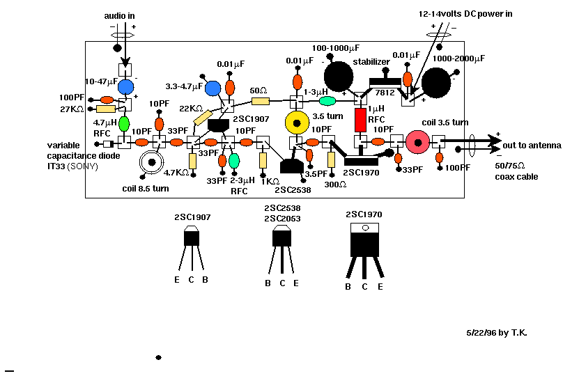
1.Some of unfamiliar parts
Q:Do the coils have an air or ferrite core?
A---ferrite core
Q:The chokes RFC's- I noticed that I can buy two chokes of
the same value in microH, with different frequency characteristics.
Is there a preferred type?
A---Higher frequency characteristics will be preferable.
Q:What type of varicap diode is required?
A----I use "1T33" (SONY). The capacity is 16.71 - 17.04 pF. I think
there are quite a lot of potions.
Q:When I build the final stage, is the 1 microH choke above the 1970
meant to be of a bigger type than the small resistor-like ones that
I'm using in the rest of the circuit?
A-----the 1970 need much ampere than the 2538 or 1907, so that it
must be bigger.
Q:Can you make sure of the position for the transistors to be soldered.
A-----That's all:
2sc1970 E - to earth plate
C - to 1microH RFC
B - to 10pF cap. and 300ohm res.
2SC2538 E - to earth plate
C - to 10pF,3.5pF and coil
B - to 1K0hm res.
2SC1907 E - to 33pF, 33pF, 10pF, 2-3microH RFC
B - to 33pF, 33pF, 22Kohm, 4.7Kohm res.
C - to 3.3-4.7microF cap.
3.Tuning and Testing
Q:How can I start transmitting?
A-----(1)Don't supply the power (12 volts DC) before connecting
the appropriate antenna (even if it is a simple coax cable antenna
that I made instantly).
(2)You must decide the frequency you want to transmit. Please check
if 88MHz, the leftist (not ideologically but literally!) frequency
of FM dial is free or not. If not, check which frequency is free
near by 88MHz. Usually you can get free space around here. Also,
the lower frequency is better for transmitting efficiency.
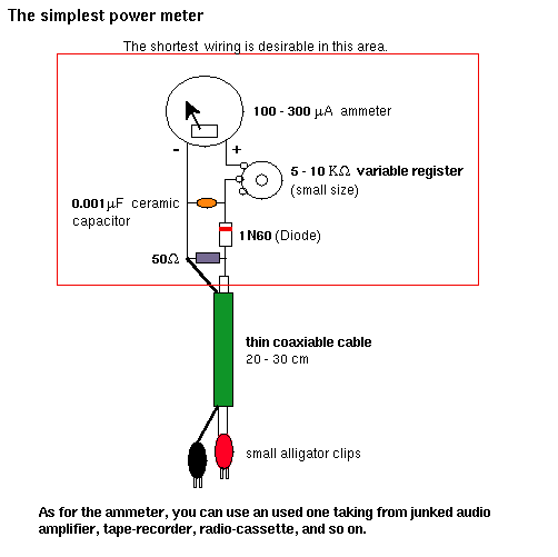
(3)Before connecting the antenna to the final output (where 100pF
is connected), you must adjust the final 3.5 coil. In order to do
so, you need a power meter.
The diagram is here and you can make it easily. Very simple diagram
with a couple of capacitors and register.
Q:What is the function of the 3.5 turn coil above the 2053? It does
not seem to have much effect on the quality of the sound on my receiver
when I move the core.
A-----This is for adjusting the matching with the original signal.
The reason may be that the matching is not correct or the coil is not
appropriate.
4.Problems:heated transistor, noise
Q:When I tested the completed circuit, the 2053 gets very hot after
a minute or two. I assume this might damage it if I let it get too
hot. Do I need to adjust the loading on the 2053, so it passes less
current? Do you have any ideas how I may get the best output - i.e.
where to connect aerial and if any parts need adding or changing?
A----When you have too hot temperature at 2SC2538 (when the
adjustment of the final coil is complete, it will not become hot,
anyway), you may exchange 50 ohm (I suggested to change before) at
2SC1907's C for 100 ohm. This means to reduce the power voltage to
the first section.
Q:Can I use an "AC adopter" for 12 volts?
A----You can, but sometimes it may cause hum nose. So get a 12 volt
power supply of over 1A (1000 mA) direct current with good quality.
5.Antenna
Q:What type of antenna will I need?
A----I suggest that first you buy a ready made FM antenna for
88-108MHz (not for TV).
I think you can get it at Radio Shack or equivalent. Please tell
them "I want to receive week airwaves of FM radio", then they will
show you some model. Every receiving antenna can be used for
transmitting as well.
When you buy it, please get the cable to connect antenna with
transmitter. Sometimes the cable is appendant to antenna. But the
cable must be quite a thick 50 or 75 Ohm coaxial cable. You will
fix this antenna on the top of your roof and will pull the cable
into your radio room.
6.Stating up
Q:Let me know how to start the transmission up?
A----Prepare the following materials:
1. Tape recorder with mini plug cable coming from audio out.
2. 12v/over 500mA DC power supply or 12v car battery.
3. Radio antenna with enough wire to reach antenna from place of
transmission.
To build the system:
1. Connect the antenna and the transmitter using the coaxial cable
connector. Make sure the connection is right; if you use it without
doing so, the power transistor may get damage.
2. Connect the audio cable from the headphone jack or line out to
the audio in on the Black box (check that the volume is down on the
tape player).
3. Everything OK? If so, connect the 12v power to the transmitter
(never mix up plus and minus!).
4. Start your tape player, tune your radio to the transmitting
frequency (89.1MHz) and you will find the signal. Bring up the
volume little by little until you've reached the appropriate level.
Now you are an independent narrowcaster.
7.How to decrease the output power?
Q:Is it possible to have much simpler and smaller powered transmitter?
A----You can cut out the final stage (2SC1970, 1 micro H RFC and etc.)
if you will transmit the signal in smaller area like in a square or so.
Theoretically:
Remove 300 ohm;2SC1970; 1 micro H. RFC;10 pF, and shortcircuit between
10 pF (from 2SC2053's terminal C) and the final 3.5 T coil (where
33pF is connected along with the final 3.5 coil).
Exchange the second 3.5 coil for 1 micro H. RFC.
Practically:
the distance between the 10 pf and the final coil is too far and
will have trouble such as self-oscillation. So, you must move
the final section closer to the second section.